- Camera basics
- Table of contents
- What is a camera?
- The pinhole camera
- $$ \begin{bmatrix} uw\ vw\ w \end{bmatrix}
- $$ \begin{bmatrix} x\ y\ z \end{bmatrix}
- $$ \begin{bmatrix} uw\ vw\ w \end{bmatrix}
- Sensor
- Coordinates
- Technologies
- CCD
- CMOS
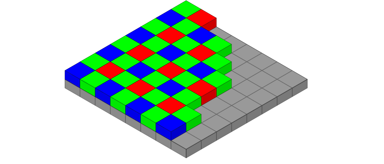
- Bayer filter
- Lens
- Distortion
- Aperture
- Shutter
- Mechanical shutter
- Electronic shutter
- Photography basics
- The 3 parameters
layout: default
title: Camera basics
nav_order: 2
mathjax: true
Camera basics
{: .no_toc}
Table of contents
{: .no_toc .text-delta }
- TOC {:toc}
What is a camera?
A modern definition of a camera is any device capable of collecting light rays coming from a scene, and recording an image of it. The sensor used for the recording can be either digital (e.g. CMOS, CCD), or analog (film).
The pinhole camera
The term camera is derived from the Latin term camera obscura, literally translating to "dark room". Earliest examples of cameras were just that; a hole in a room/box, projecting an image onto a flat surface.

Using only a small hole (pinhole) blocks off most of the light, but also constraints the geometry of rays, leading to a 1-to-1 relationship between a point on the sensor (or wall!) and a direction. Given a 3D point
in which
Let's make the sensor coordinate system more general, by introducing an origin
$$ \begin{bmatrix} uw\ vw\ w \end{bmatrix}
\begin{bmatrix} f_x & 0 & u_0\ 0 & f_y & u_0\ 0 & 0 & 1 \end{bmatrix} \begin{bmatrix} x\ y\ z \end{bmatrix} := K \begin{bmatrix} x\ y\ z \end{bmatrix} $$
The matrix
$$ \begin{bmatrix} x\ y\ z \end{bmatrix}
\begin{bmatrix} R_{11} & R_{12} & R_{13} & t_x\ R_{21} & R_{22} & R_{23} & t_y\ R_{31} & R_{32} & R_{33} & t_z\ \end{bmatrix} \begin{bmatrix} x_w\ y_w\ z_w\ 1 \end{bmatrix} := \begin{bmatrix} R | t \end{bmatrix} \begin{bmatrix} x_w\ y_w\ z_w\ 1 \end{bmatrix} $$
where
$$ \begin{bmatrix} uw\ vw\ w \end{bmatrix}
K \begin{bmatrix} R|t \end{bmatrix} \begin{bmatrix} x\ y\ z\ 1 \end{bmatrix} $$
When using more than one camera, it is useful to have a single world coordinate system while letting each camera have its own sensor coordinate. As explained in the next section, if intrinsic and extrinsic parameters are known for every camera looking at the scene, 3D reconstruction can be achieved through triangulation.
Sensor
Coordinates
Continuous sensor coordinates make sense when simply projecting an image or recording it with a film. If using a digital sensor, a natural choice for the sensor coordinate system is the pixel indices. Those discrete, unitless values can be related to the physical sensor by defining an equivalent focal length in pixel units:

The image plane is an imaginary construct sitting in front of the sensor, at one focal length (in pixels) away from the camera's coordinate system. Because it sits in front of the camera, the image is upright again.
It is common to choose the
Technologies
We'll focus on the two main families of digital sensors: CCD and CMOS.
In both families, the actual light sensing is based on the electron-hole pair generation in MOS devices.
CCD
In CCD sensors, the generated charges in the photodiodes are accumulated under a potential well, controlled by a voltage on the gate.
Charges can be moved to a neighboring pixel by performing a specific sequence on the gates. By shifting the charges all the way to the edge of the sensor, individual pixel values can be readout sequentially.
Advantage of CCD sensors include the simplicity of their design, and the large surface dedicated to sensing light. One disadvantage is the readout speed bottleneck caused by using a single decoding unit.
CMOS
Bayer filter
Lens

Distortion

Aperture

Shutter
Mechanical shutter
Electronic shutter
Photography basics
The 3 parameters
- Aperture
- Shutter speed
- ISO
Each parameter can be converted to a