Desktop Wire-EDM
Past Work:
Three years ago I built this:
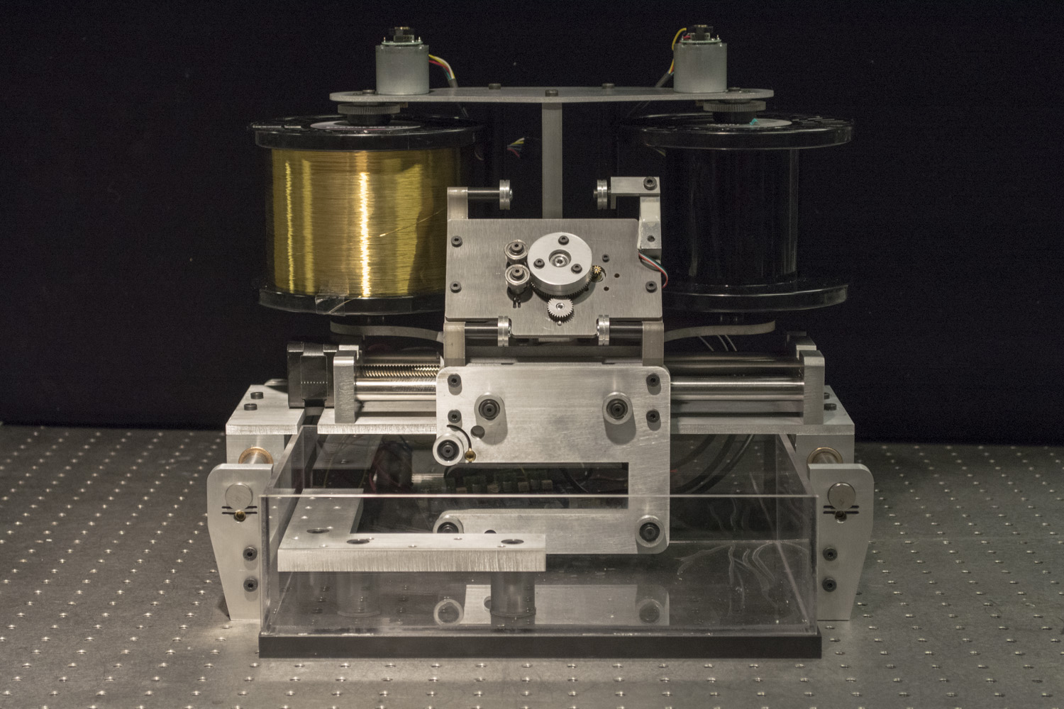
It looks nice… all the subsystems are there but it just hasn't been integrated.
The two biggest missing parts are: the pulse generator, and the controls. I'll go ahead and describe what I got up to and talk through what I'd like to try this semester to get this thing going.
Pulse Generator
This is what we're making:
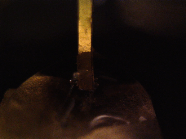
When I last tried this, I did manage to see some sparking:

My last circuit looked something like this:

Which became a sort-of kludegy board:

Since then, I've thought about this every now and then, and think I understand the circuit I need a little better now.
I've had some email correspondance with Jaako Fagerlund (who is one of the few people who has made his own desktop EDM) and he had a really nice explanation of how the waveform should work:
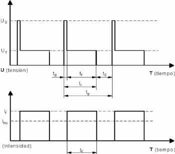
The waveform is quite simplified in that picture, but it explains the basics very well. Looking at the upper graph you see gap voltage versus time. As the voltage is switched on, the voltage in the gap is the same as the generators output. If the gap is small enough, the dielectric breaks down and a spark is ignited. This plasma channel is of course lower resistance, so now current (lower graph) starts to flow. The gap voltage drops to basically what the plasma channels resistance times current is. In the graph this area is the lower voltage after full (open) voltage. Then after the on time pulse length is achieved, the generator switches of, the current flow stops and the gap voltage is zero until the generator once again applies a new pulse.
Based on this, this is the basic circuit schematic that I'm after:
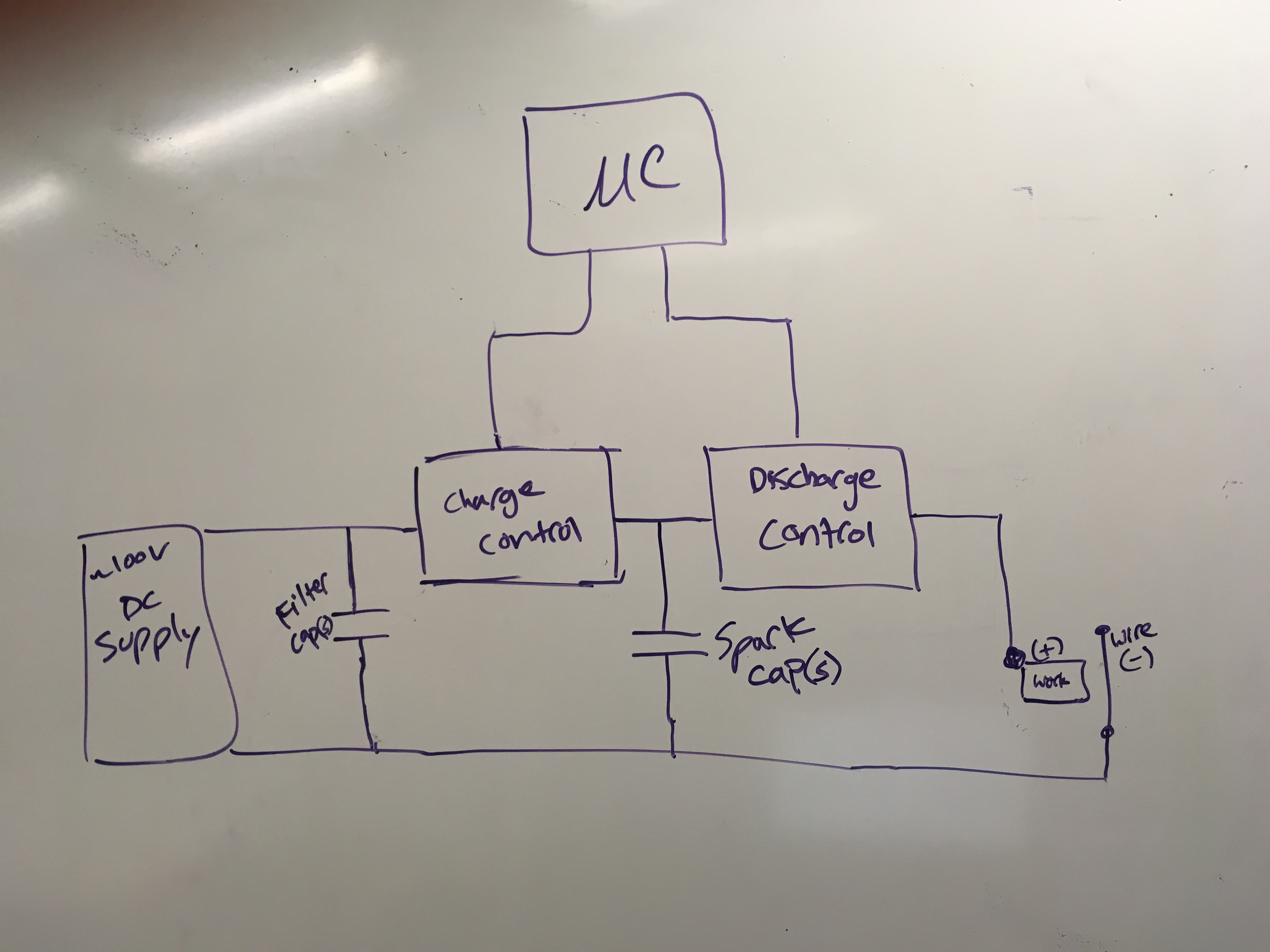
With a few more details filled in:
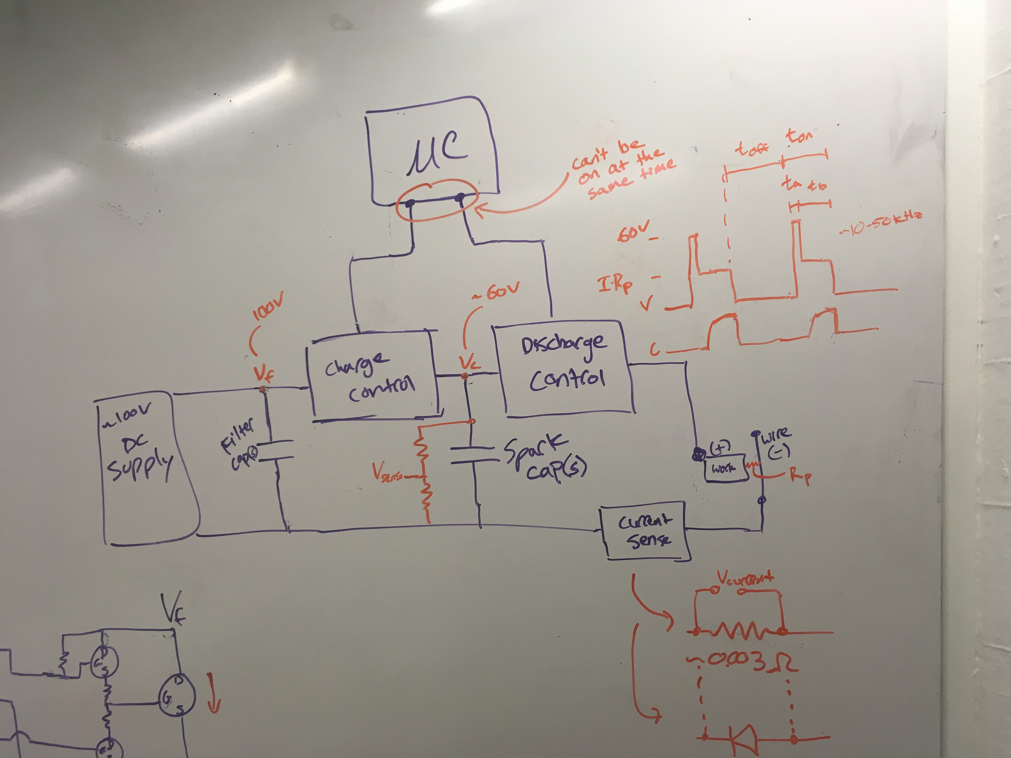
My understanding of the waveform:

I'm collecting references:
I've started picking out parts:
-
Hearty N-Type MOSFETs: IRFP460A FDB20N50F SDB45N40 (least R_dson)
-
High-side gate drivers: LM5107 UCC27200A
- I could get away with just using one of these (and using a low-side mosfet to do the discharge control). The problem with this is that then the workpiece and worktable are at high voltages whenever the machine is on. So I suspect I'll go with two...
-
Capacitor: 6.8uF conductive polymer
-
3.3V switching regulator: https://www.digikey.com/scripts/DkSearch/dksus.dll?Detail&itemSeq=254721636&uq=636571622259993391
-
window comparator
Timing Calculations
from: https://www.vishay.com/docs/73217/an608a.pdf
Effective Resistance seen by the gate driver: $ R_G = R_g + R_{gext} $
Effective capacitance seen by the gate driver: C_{iss} = C_{gs} + C_{gd}
switching time: $ t = R_G C_{iss} \times \ln{\frac{1}{1-V_{gs}/V_{GS}}} $
Design Decisions
I decided to focus the first revision of this board around the idea of doing as much as possible in firmware on a microcontroller rather than as a static implementation in hardware.
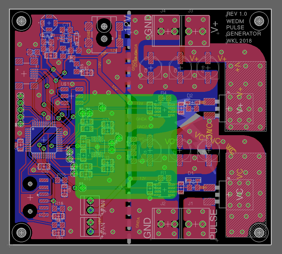
After much flipping back and forth between datasheets, digikey tables, and eagle libraries, I eventually ended up at this board:
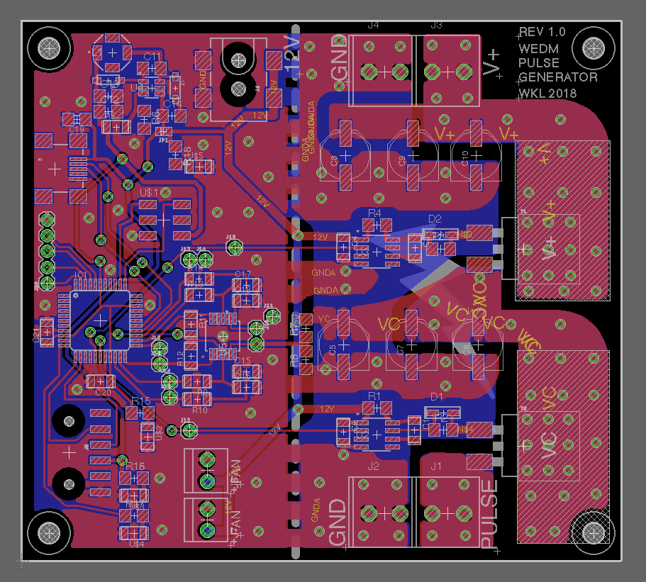
I've more-or-less tried to keep the board layout pretty divided based on function. This will hopefully help with debugging and I believe is also good design practice when dealing with mixed signals (both digital/analog and high-power/low-power).
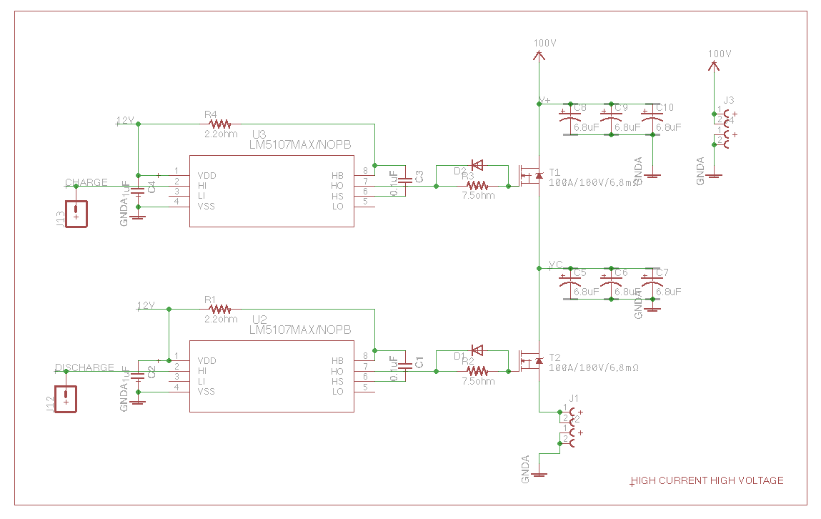
All of the high-current/high-voltage things are on the right side of the board. This includes the two power MOSFETs (SDB45N40), two banks of low ESR capacitors (6.8uF conductive polymer), as well as the high-side gate drivers (LM5107). 100V DC power comes in at the top of the board, which will likely just be supplied by a bench top 100V supply initially (although, ultimately I may take mains power in and use a bridge rectifier to get that voltage).

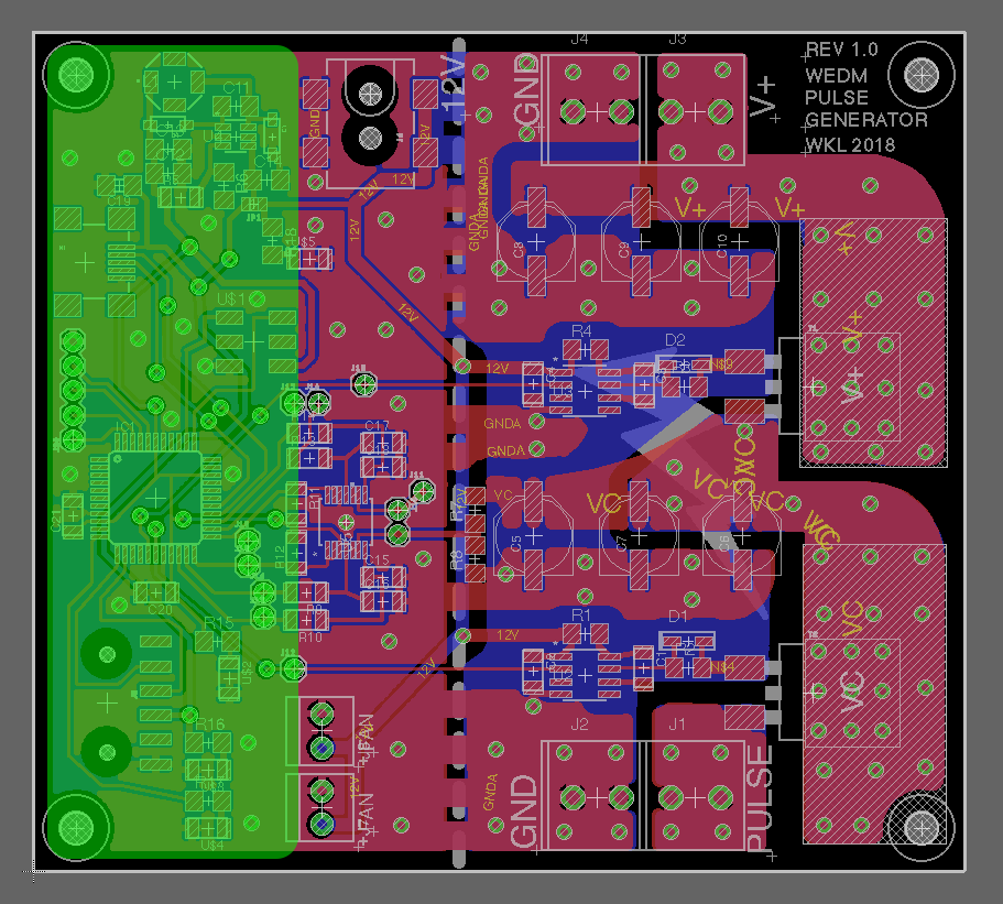
On the opposite side of the board are all of the small-signal computing and communication peripherals. I decided to use an xmega128a4u as the main processor. I chose this over other options (including the NRF52, ATSAMD21, ATSAMD51, ATmega32u4) for it's speed and ease of timing. After talking with Sam and Jake, the ATSAM architectures just seemed a little unnecessarily complex for this dedicated controller. Some of the notable features of this XMega include a 2 Msps analag to digital converter (which may just be fast enough to directly sample my ~50KHz pulses), two built-in analog comparators, and all of the necessary PWM/timing peripherals. Because I had space, I included both USB and FTDI communication channels (since I've never tried getting USB going on an XMega before). I also broke out a few extra GPIO/ADC pins… just in case...
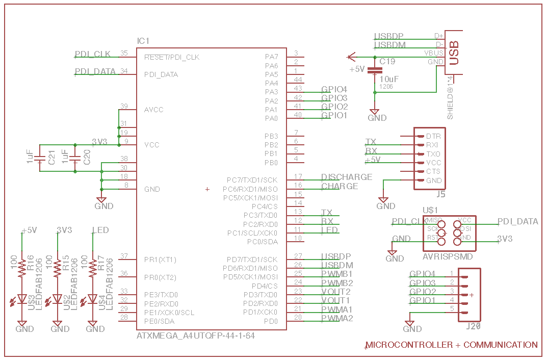
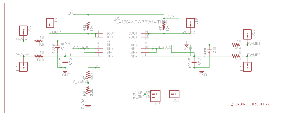
Connecting those two regions, is the sensing and control circuitry. This region needs to be able to sense the voltage levels of the spark and filter capacitors relay information to the microcontroller to decide whether to turn on or off the high-power MOSFETs. I'm using a 4-channel comparator wired as a dual window-comparator. This will let me set desired voltage windows (across the spark capacitors) that I can then modulate the MOSFETs to achieve. I plan to produce the variable voltages by low-pass filtering PWM signals from the microcontroller. This is just one idea I have for implementing this kind of control and I intentionally left my options open for experimenting.
Controls
To control the Wire-EDM, we can't just simply use a standard g-code interpretter and machine controller since the motion of the axes needs to depend on how quickly/slowly the material is being eroded.
So, I plan to piggy-back off of some of Jake and Sam's recent stepper motor boards to implement the path planning and control.
This will involve things like the Bresenham line algorithm to discretize non-rectilinear motions and map into movements of the individual motors. Fortunatley, I suspect I won't have to worry too much about acceleration/jerk control given that this machining process is relatively slow.
We can tell how much material has eroded and how large the gap between the wire and workpiece is by sampling the voltage across the spark capacitor. In the limit where the gap is large and there's no spark, this voltage will be the same as the voltage determined by the charge control circuitry. At the other limit, where the wire actually touches the workpiece, there is a short circuit and there's no voltage across the capacitor.
What I'm not sure about is exactly how fast I want to be able to step to react to changing gap voltages. Many circuits I've seen elsewhere use op-amps configured as a window comparator to servo the stepper motors based on the gap voltage. I will probably start by trying to implement this in firmware with something like an NRF52. With this microcontroller, I can use things like the PPI system to have events triggered automatically without bogging down the main-code.